When compiling the HDL code, FSM Compiler and FSM Explorer come into picture. These tools hugely optimize the resource used by the logic in terms of space and timing.
FSM Compiler :-
-> It automatically detects state machines in the source code.
-> Implements the state encoding depending on the number of states present in the state machine, i.e.
a) 0-4 states :- Sequential encoding.
b) 5-24 states :- One hot encoding.
c) >24 states :- Gray encoding.
-> Performs reachability analysis, i.e.
a) optimize away all state that can't be reached.
b) optimize all transition logic that can't be reached.
FSM Explorer :-
-> Uses Finite State Machines extracted by the FSM Compiler.
-> Runs through each encoding style as discussed in the FSM Compiler segment. And this tool will select the best (most performant) implementation.
Sunday, July 31, 2011
Nepal Telecom ADSL settings for PLANET router
The steps to follow are:-
1) Connect the computer to the router via a point to point connector.
 Point to Point connector
2) Setup the wired lan connection with the router.
3) Access the router.
Do this by opening any internet browser, i.e. Goolge Chrome or Internet Explorer, or Mozilla Firefox, etc. and type in http://192.168.1.1.
4) In the Network Section, click on WAN.
5) Fill the fields with values as shown in the following pic. :
In the username and password (shown by the green ellipses) fill in the details as provided by the Nepal Telecom.

6) Click on the Save button given at the end of the page.
7) Then goto Admin section and click on commit/reboot. Click on Reboot.

The system will go for a reboot. When the router comes up, you will be able to access the internet. Yippie ! ! !
1) Connect the computer to the router via a point to point connector.

2) Setup the wired lan connection with the router.
3) Access the router.
Do this by opening any internet browser, i.e. Goolge Chrome or Internet Explorer, or Mozilla Firefox, etc. and type in http://192.168.1.1.
4) In the Network Section, click on WAN.
5) Fill the fields with values as shown in the following pic. :
In the username and password (shown by the green ellipses) fill in the details as provided by the Nepal Telecom.

6) Click on the Save button given at the end of the page.
7) Then goto Admin section and click on commit/reboot. Click on Reboot.

The system will go for a reboot. When the router comes up, you will be able to access the internet. Yippie ! ! !
Motor control via parallel ports of a PC : A failed project
It was the summer of 2007, when a friend came with a proposal. A proposal to build a control system to control the movement of an object along a fixed straight line. The object had to be moved to a certain distance from the initial location along a straight line.
I took up the project and used a simple motor control logic to build the system. The computer parallel ports were used to send the control signals to the motor. The motor and control signals were in fact isolated by the optocoupler. These are electrical isolaters, which isolate the current from computer to the ones in the motor. The main purpose of its use is to isolate the back current from the motor from reaching the computer ports. Without isolation, the computer ports would just burn away upon significant back current.
The motor then controlled the distance that would be covered by the object from its original location. A simple screw would convert the rotational movement of motor to linear movement of the object.
When I tested the whole circuit to control the objects' movement using my computer, it worked great.

But, when I took the circuit and tried to run the same code in Lab's PC, it showed a random behavior. I tried to debug it but to no avail. The motor would move the object to a random location when the computer sent the control signals.
I took the circuit back to the room and checked. It ran perfectly.
Even after several debugging sessions, I couldn't know the exact reason of the failure of the circuit.
Tuesday, July 26, 2011
Compiling top file in the beginning during Simulation in Verilog
Generally, we tend to compile the top verilog design file at the end, i.e. after compiling all other sub-blocks. Although this is a very good practice while synthesizing the code, you may face problems during synthesis and simulation if you are using `defines in your code to instantiate modules or signals conditionally.
Follow the following example:-

If you compile the sub block first and then compile the top block, then the output would be an OR gate. That is because, when the sub-block is being compiled, ANDGATE is not defined as yet. So, the OR gate would be instantiated.
But, if you compile the top file and then compile the sub-block, then AND gate would be instantiated, as the sub-block detects the ANDGATE to have been defined earlier.
So, it is a good practice during simulation, to compile the top block before the sub-blocks.
Friday, July 22, 2011
Do not use % in the verilog code during Verilog Synthesis
When you need to find the remainder of a division operation, then %, i.e. Mod, is used. Suppose you want to find the remainder when 4 is divided by 3 then the code to implement is :-

When you are designing complex logics, use of Mod or % makes your work easier and also the code is more readable. The simulation of code with use of % works fine. But, when you move to synthesis, the code takes up so much time to synthesize. And honestly, I don't know if it will ever synthesize. I had a piece of code with % used at multiple places. After waiting for 40 odd minutes, the synthesis just stuck at 80%. It was trying to synthesize but I couldn't wait longer. After removing the % from the code, I got the whole code synthesized in less than 10 minutes. :)
So my advice to all the verilog coders will be to Feel free to use % if the code is meant for simulation. But Avoid usage of % in code that is to be synthesized. Rather use if..else statement, however lengthy they may be.
Verilog Simulation : Sensitivity list for a combinational logic
An interesting find today while I was simulating a big chunk of code. The problem occurred in the combinational always block. By rule, we have to put all the inputs to the combinational block in the sensitivity list.
Eg for a simple and gate with input inpA and inpB and output as outAndAB, the coding goes as:-

And if you simulate this design, the code will work fine. But when you move to complex combinational block designs, it is easier and better to assign * in the sensitivity list. In my design I had similar code implemented in three places. While the two worked fine, I got issues in the third implementation. The output didn't get modified when the input changed even though the inputs were there in the sensitivity list. I tried putting the *, which means all, in the sensitivity list and it worked. The tool will optimize the * and put all required signals in the sensitivity list when simulating the code.
After the change the code for the And gate will be :-
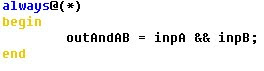
So, remember to always put * in the sensitivity list of a combinational block.
Monday, July 18, 2011
Default values of Reg and Wire in Modelsim Simulation
Ever wondered what is the default value assigned to a reg or a wire during simulation?
Well, a reg has a default value of HiZ (High Impedance) while a wire has a default value of X (Don't Care) in Modelsim simulation.
Verification :-
a) Input Module :

b) Output Waveform :

*Note:- Simulation results of Modelsim SE 10.0
Well, a reg has a default value of HiZ (High Impedance) while a wire has a default value of X (Don't Care) in Modelsim simulation.
Verification :-
a) Input Module :

b) Output Waveform :

*Note:- Simulation results of Modelsim SE 10.0
Run TCL file in Modelsim
Testing of logic designs in Modelsim can be automated using TCL files. To run TCL file in Modelsim, follow the two simple steps :-
Step 1 :- Write the TCL file.
Step 2 :- Open Modelsim. Goto Tools -> Tcl -> Execute Macro. And then select the tcl file.

Step 1 :- Write the TCL file.
Step 2 :- Open Modelsim. Goto Tools -> Tcl -> Execute Macro. And then select the tcl file.

Sunday, July 17, 2011
Computer Systems : Internal hard disk drive not found
I got this error while booting up my Dell Latitude. The screen said that the system could not find the internal hard disk drive. I was in shock. I tried googling up the issue but to no avail. I even jacked out the system RAMs and cleaned its connectors. I also removed the battery and put it back after few minutes.
After these failed approaches, I entered the BIOS setup to see if the BIOS is actually reading the hard disk or not. If BIOS can't read it then its time to buy new hard disk. With lots of combinations and permutations, I finally hit the nail's head.
I solved the problem in two simple steps:-
Goto the BIOS setup page. This page may look different based on the Dell laptop model.
Step 1 :-
In the Boot Sequence, which is inside the General Settings, move the Internal HDD to the top. This will ensure that the system will first look up into the internal HDD for boot programs. By default, the floppy disk(diskette) drive is set to highest priority.

Although this is not a major problem, but setting internal hdd as highest priority will not have any side effects, as the laptops these days lack the floppy disk drives, which are set to the highest priority in default conditions.
Step 2:-
Next goto the SATA Operation settings, which could be in System Configuration or the Device Info depending upon the laptop model. Set this to ATA.

Why does this problem occur?
Due to improper shutdowns or deletion of files in the windows folder, the BIOS settings would have modified. As the SATA operation setting, that defines the operation of hard disk, is set to some other than ATA, the system can't read the hard disk.
Notes:-
1)This problem was faced in Windows XP and thus could/couldn't work on other Operating systems.
2)The solution worked on Dell Latitude and Inspiron laptops. For other models, you need to verify.
Friday, July 15, 2011
Bash : syntax error in expression (error token is "12")
If you want to read a file line by line then you can follow the post in the link
When you echo this line to the display or to another file, then there seems to be no issues. But, when you try to store the line contents to a variable,
Eg:-
temp=$line
then you could get the error :-
syntax error in expression (error token is ".....")
This error occurs if the file, from which we are reading the lines, contains carriage return-line feed . The solution to this problem would be to strip the carriage return-line feed from the $line when it is being assigned to temp variable.
Solution :-
temp=${line//$'\r'}
Remember, if you want to assign temp again to another variable, then too you have to follow the same syntax of assignment as given in the solution.
Reading a file word by word in bash
Reading a file word by word in bash can be done in the following two steps :-
Step 1:- Read the file one line at a time and buffer it

Step 2:- Read the buffered line one word at a time
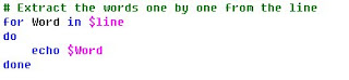
So, combining the two, we can read a file word by word. The final code is :-

Step 1:- Read the file one line at a time and buffer it

Step 2:- Read the buffered line one word at a time

So, combining the two, we can read a file word by word. The final code is :-

Sunday, July 3, 2011
Verilog :- Why not to use Blocking Statements in Sequential Logic Design
Although there is no golden rule in verilog as to which type of statements to use while designing sequential circuits, it is highly recommended that non-blocking statement be used while designing such circuits.
It is a very good and almost an essential practice to use blocking statements to design combinational block and non-blocking statements to design sequential logic.
When you have multi-cycle paths to be designed as a sequential logic, then the use of blocking statements usually leads to optimisation/trimming of the logic. For a 2 cycle delay, you will only get a single cycle of delay. Consider the following example :-
Case 1:- Sequential logic design with non-blocking statements:
Code:-

Rtl Schematic :-

Case 2:- Sequential logic design with Blocking statements:
Code:-

Rtl Schematic :-

So, non-blocking statements should be used while designing Sequential blocks in Verilog.
*Note :- The synthesis of code and rtl schematic generation were done using Xilinx ISE Release Version : 9.2.04i
Subscribe to:
Posts
(
Atom
)
